The Application Mapping plugin will copy application records from the source object to the target object. In addition, it also designates vehicle and part type references to the newly created target application records. The Application Mapping plugin is added and configured in the Onboarding Mappings Details Screen for the selected Mapper Configuration.
Prerequisites
There are terminology variations within the Application Mapping plugin for each standard.
For example:
- The AutoCare addresses terminologies like Vehicle, Part Terminology, and Part
- The TecDoc addresses terminologies like Assembly, Generic Article, and Article
- Some users will have their application records applicated to vehicles, assembly, or engines, which they commonly address as targets
Despite these differences, the overall functionality that allows users to onboard application records remains the same. For ease of understanding, this topic is documented with an example where the user onboards application records from AutoCare standard to the NAPA standard. For more information about variations across different standards, refer to the PMDM for Automotive Terminology topic within the Automotive Reference Guide here.
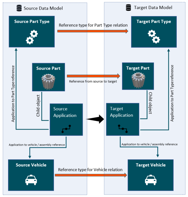
Before creating the Application Mapping plugin, the following items must be done:
- Ensure that there is a reference established between the object type of the source application record and the object type of the vehicle
- Ensure that there is a reference established between the object type of the source application record and the object type of the part type
- Establish a reference between the object type of the source part and the object type of the target part
- Establish a reference between the object type of the source vehicle and the object type of the target vehicle
- Establish a reference between the source part type and the target part type
Configuring Application Mapping Plugin
To configure the Application Mapping plugin, follow these steps:
- With the required Mapper Configuration selected, click on the New mapping button available within the Mappings tab of the Onboarding Mappings Details screen.
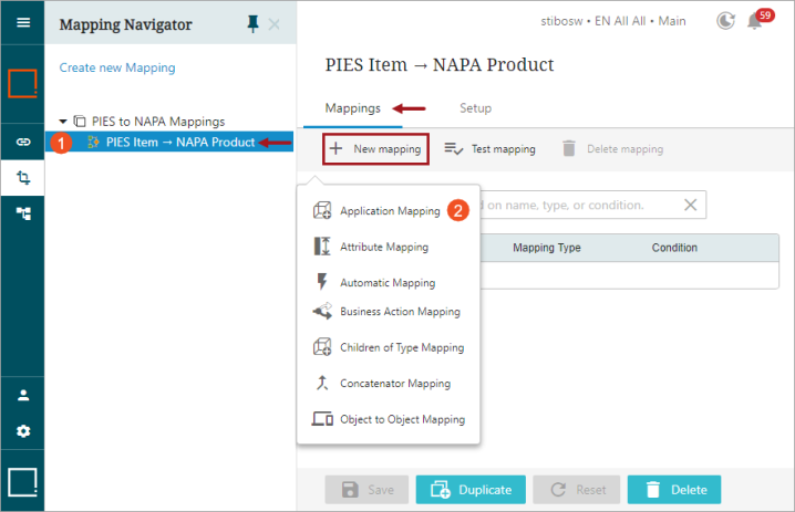
- Selecting the Application Mapping will display a layout split into two tabs called 'Relations' and 'Settings.' While the Relations tab allows users to add new mapper rows, the Settings tab comprises all of the parameters that belong to the Application Mapping plugin. Users should first configure the necessary parameters in the Settings tab before adding any mapper rows in the Relations tab.
Below is the screenshot of the Settings tab for the Application Mapping plugin in the Onboarding Mappings Details screen. The steps required to configure the Application Mapping are denoted with a number in the screenshot. Below the screenshot is a numbered list that describes each step, corresponding to the number shown in the image.
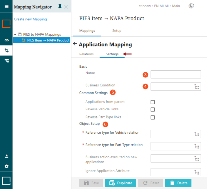
- Type in a suitable name next to the Name field. This could be any unique name that describes the mapping functionality.
- The Business Condition parameter allows users to select a business condition. The selected business condition runs the mapper plugin only on the object if the condition is true.
- Populate the parameters available under the Common Settings field as explained below:
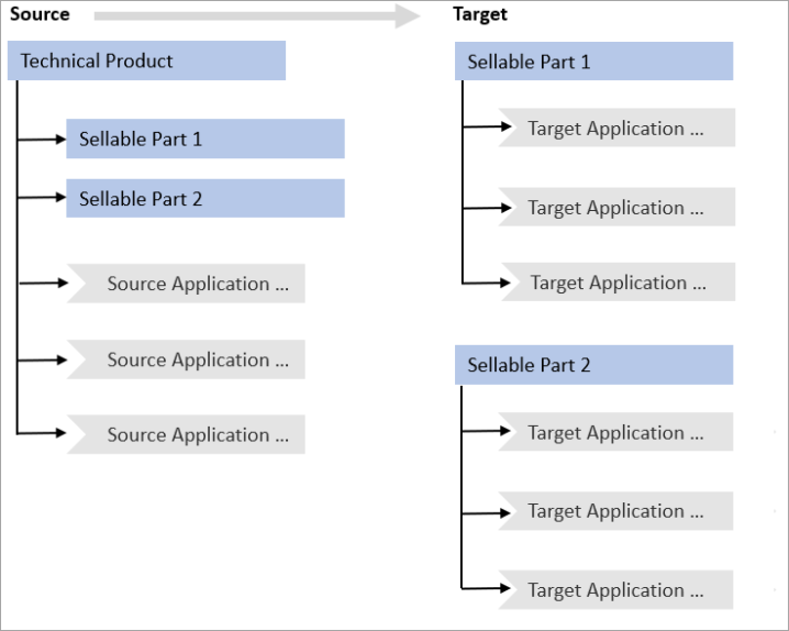
- Applications from parent: This parameter is to be enabled only if the source part and the application is on the same level in the hierarchy. Meaning, source application records reside directly below the parent of the source part. However, the execution of such a Mapper Configuration will create the application records below the target part object itself.
Below is an example of such a use case where the sellable parts which inherit all relevant technical product information are modeled to reside as children of the 'Technical Product' ('Technical Product' is an object where all technicalities of a product are maintained). The 'Technical Product' object is applicated, and all application records created therefore become the siblings of the sellable parts. When the application records from the source are onboarded with the 'Applications from parent' parameter selected, the application records are created below the target sellable part (as shown below).
- Reverse Vehicle Links: This option is selected if the reference configured within the 'Reference type for Vehicle relation' field is in the direction from the target to source vehicle (as shown below) and the user wants to change the direction of the reference. This is the same as selecting the target vehicle and using the [Referenced By] option.
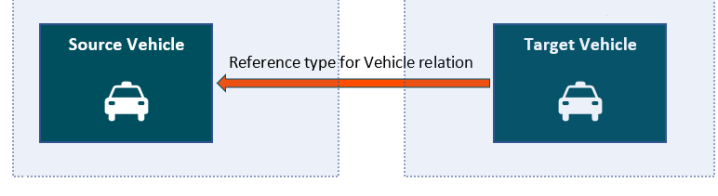
Consider an example mapping setup where the application records belonging to the source object 'PIES Item' are to be onboarded to the target object 'NAPA Product.' Usually, the reference type that establishes the vehicle relationship will be directed from source vehicle 'Base Vehicle' to target vehicle 'NAPA Year.' However, if the reference type is directed from target vehicle 'NAPA Year' to source vehicle 'Base Vehicle,' then instead of creating a new vehicle relation reference type, users can select the Reverse Vehicle Links field to establish the right direction of vehicle relationship.
- Reverse Part Type Links:This option is selected if the reference configured within the 'Reference type for Part Type relation' field is in the direction from the target to source part type (as shown below) and the user wants to change the direction of the reference. This is the same as selecting the target part type and using the [Referenced By] option.
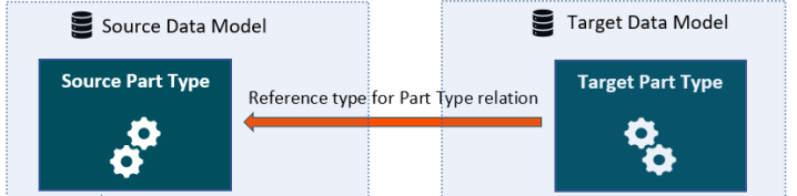
For example, if there is a mapping setup where the application records belonging to the source object 'PIES Item' are to be onboarded to the target object 'NAPA Product.' Usually, the reference type that establishes the part type relationship will be directed from source part type 'Part Terminology' to target part type 'NAPA MPCC.' However, if the reference type is directed from target part type 'NAPA MPCC' to source part type 'Part Terminology,' then instead of creating a new part type relation reference, users can select the Reverse Vehicle Links field to establish the right direction of part type relationship.
- Populate the parameters available under the Object Setup field as explained below:
- Reference type for Vehicle relation: Defines which reference type to use to look for the vehicle relationship from the source to the target vehicle.

For example, suppose the source object is PIES Item and applications belonging to this source object need to be mapped to target object 'NAPA Product.' In that case, the reference type for vehicle relationship is referenced from source object vehicle = Base Vehicle to target object vehicle = NAPA Year.
- Reference type for Part Type relation: Defines which reference type to use to look for the part type relationship from the source to the target part type.
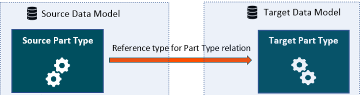
For example, if the source object is PIES Item and applications belonging to this source object need to be mapped to target object 'NAPA Product,' ,then the reference type for part type relationship is referenced from source object part type 'AutoCare Part Terminology' to target object part type 'NAPA MPCC.'
- Business action executed on new applications: This field allows the user to select a Business Action. The selected business action will be executed only on the new application records created while running the Mapper Configuration.
While creating a business rule to be used in this parameter, it is recommended that the following binds be used as necessary along with the other standard binds as required:
|
Bind |
Functionality |
|---|---|
| Mappings Manager |
When the Mapper Configuration is being executed, it is quite likely the actual new child node is not created in the target yet. This means the business rule cannot use the Current Object bind. Instead, the business rule must use the Mappings Manager bind that has only one method addValue(DataType datatype, String Value). This allows the business rule to create new references and set attribute values on the child object. It is not possible to create new objects through the Mappings Manager bind. |
|
Source Object |
Used to retrieve data specific points from the source object |
| Source Children |
The set of children (objects) that are merged into the new target child. The set always contains at least one object. |
-
Ignore Application Attribute: This field allows users to select an attribute that is valid for the source application record. The selected attribute determines if the application record needs to be onboarded when the Mapper Configuration setup entity is executed on the source object. If the selected attribute belonging to the source application record holds the value 'true', then such application records will be skipped from being onboarded.
For example, if the user wants to skip the application records from being onboarded that are marked for deletion, then the attribute used for flagging the deletion of the application record is configured in this parameter.
Setup entity definitions can be exported as comments and submitted to an external source control system for comparison purposes. For details, refer to the Configuration Management documentation.
- Once all the necessary parameters in the Settings tab are populated, the users must define a relation for retrieving information from the source and copy it to the target. Users can navigate to the Relations tab and add new mapper rows to the Application Mapping plugin to define a relation.
Click the 'Add Relation' icon, and the Mapping Guide window will display (as shown below).
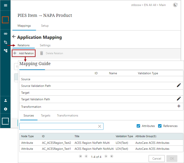
Adding a relation can be as simple as copying an attribute value from the source application over to the target application. Or for any condition(s) that can be retrieved on the source object by following references or attributes can also be added as a relation to the target object in order to map the applications (only if the valid relations are covered).
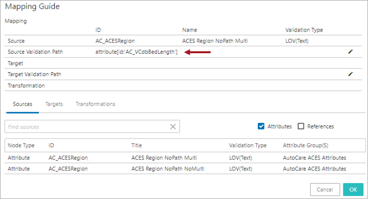
- To retrieve an attribute value of the source application record, select the Sources tab, and with the Attributes checkbox selected, start typing the initial letters of the attribute name or ID in the search field. This filters down and displays attributes that are valid for the source object's application records. Select the required attribute from the result list displayed below the search bar.
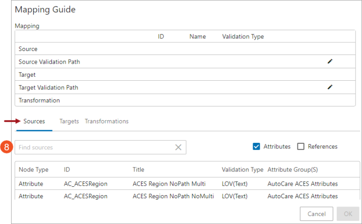
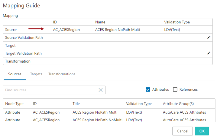
Once selected, the attribute will be populated in the Source field (as shown below)
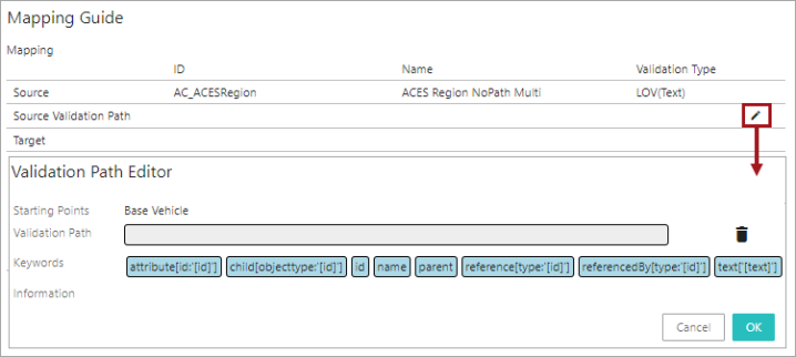
- Optionally, if any additional information (ID, Name, attribute values, references, or links) from the source object's application record needs to be retrieved, click on the Edit icon (
 ) in the Source Validation Path field, and the Validation Path Editor window will display (as shown below). If the user does not want to retrieve additional information, skip populating the Source Validation Path field and proceed with step 11 within this topic.
Within the Validation Path Editor window, the user can select specific data points from the source model by selecting a combination of the elements available in the Keywords field and thereby creating a STEP Validation path. For more information on defining the source STEP Path, refer to the Mapping Validation Path Functionality topic within this guide here.
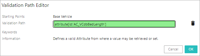
- Double click on the required element(s) from the Keywords field. The selected element will be populated in the Validation Path field (as shown below). The specific combinations of elements are chosen depending on the unique requirements for the data being retrieved. Selecting the elements will define the source STEP Path, which describes the path from which the source data must be retrieved. Depending on the element that is selected, further configurations may be required. In the example below, element attribute[id:'[id]'] is selected and displayed in the Validation Path field. The red colored field indicates that additional configuration is required.
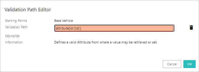
Users can add one element or a combination of multiple elements to create a source STEP Path. For more information on creating the source STEP Path, refer to the Mapping Validation Path Functionality topic within this guide here.
In this example, the selected element 'attribute[id:'[id]']' is configured to retrieve the value from attribute with ID 'AC_VCdbBedLength'.
Once selected, the source STEP Path with the defined data will be populated in the source Validation Path field.
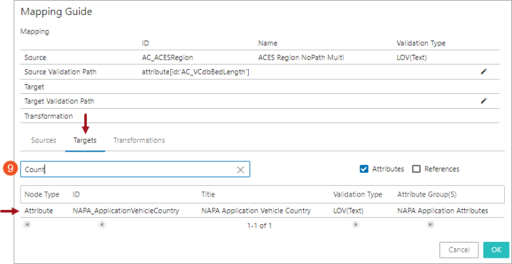
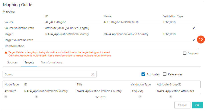
- With the 'Targets' tab selected, click in the Search field and start typing the initial letters of the attribute / reference name or ID of the target attribute / reference to which the value should be copied. Select the attribute / reference from the typeahead results displayed below the search bar.
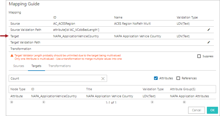
Once selected, the selected attribute / reference will be populated in the Target field (as shown below).
- Optionally, if the retrieved information from the source object needs to be populated in the specific data points of the target object, click on the Edit icon () in the Target Validation Path field, and the Validation Path Editor window will display(as shown below). If the user does not want to retrieve additional information, skip populating the Target Validation Path field and proceed with step 13 of this topic.
Within the Validation Path Editor window, the user can select specific data points from the target model by selecting a combination of the elements available in the Keywords field and thereby creating a STEP Validation path. For more information on defining the target STEP Path, refer to the Mapping Validation Path Functionality topic within this guide here.
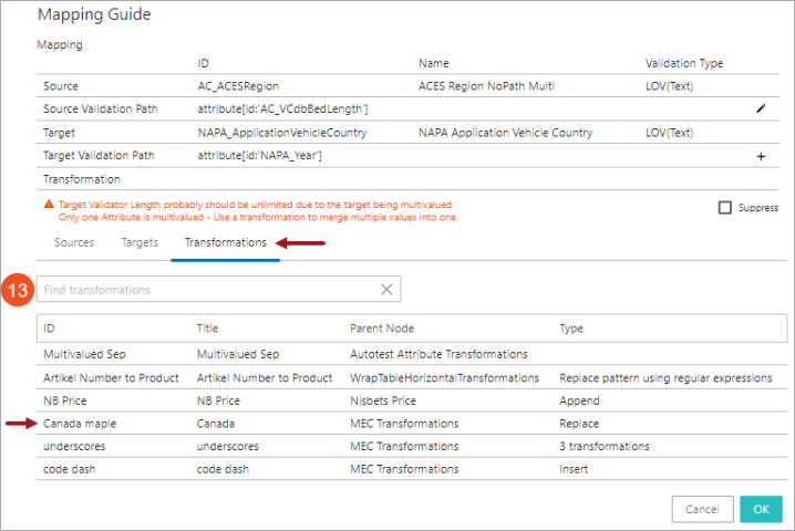
- If transformations are needed, users can either use an existing attribute transformation in the system or create a new one by clicking the 'Create new transformation' icon (
 ) available within the Transformation field. To configure an existing attribute transformation, users should select an existing attribute transformation listed in the 'Transformations' tab displayed in the lower half of the window (as shown below).
Clicking on the 'Create new transformation' icon (![]() ) available within the Transformation field will open the Transformation Overview window where the user can create a new attribute transformation. For details about creating an attribute transformation standing on a Mapping Guide window, refer to Creating Attribute Transformations Through Mapping Guide Window topic within this guide here.
) available within the Transformation field will open the Transformation Overview window where the user can create a new attribute transformation. For details about creating an attribute transformation standing on a Mapping Guide window, refer to Creating Attribute Transformations Through Mapping Guide Window topic within this guide here.
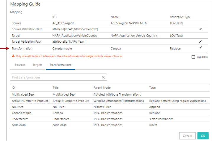
The selected transformation will be populated in the Transformation field (as shown below).
The populated transformation can be edited / removed by clicking the edit icon (![]() ) in the Transformation field.
) in the Transformation field.
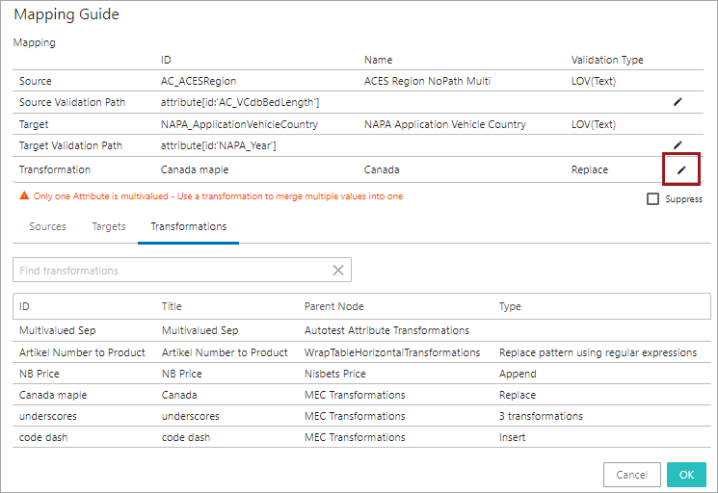
Note: Deleting an attribute transformation from the Mapping Guide window means removing it from the current mapping setup; however, editing it impacts all of the other mappings that have used the particular attribute transformation. Users are advised to be cautious before editing the attribute transformation. The Mapping Guide in the Web UI does not analyze if the transformation is applied to any other mapping.
After the source and target data points are defined, the system evaluates the validity match between the source and the target data points. A hyperlink text explaining the reason for the validity match / mismatch will be displayed. Clicking on the hyperlink opens the 'Detailed Information' dialog which displays the validity match / mismatch information of the Application mapping configuration. Below is an example of an invalid match between the source and the target attribute that is displayed in the 'Detailed Information' dialog.
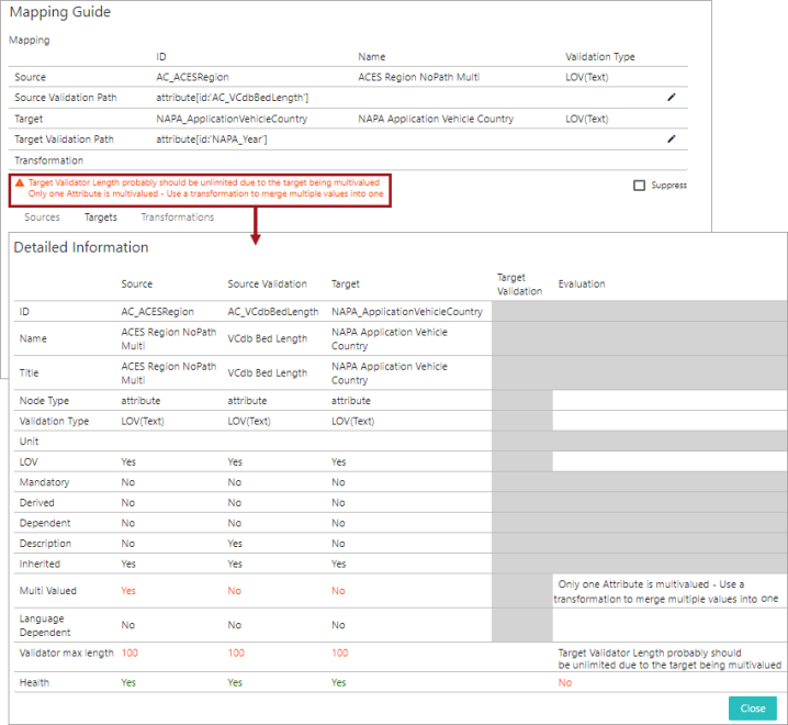
Users can suppress the validation mismatch warning message by clicking on the 'Suppress' checkbox in the Mapping Guide window. Selecting the 'Suppress' checkbox only removes the data type mismatch warnings displayed on the Mapping Guide window and does not resolve the mismatch irregularities.
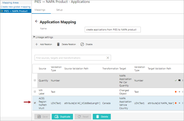
- Click OK to save and close the 'Mapping Guide' window and then click Save to save the changes. As shown in the screenshot below, the newly added application mapping row will be displayed. To edit the application mapping, click on the row to open the Mapping Guide window in which edits can be made.
- Repeat the above steps 7 to 14 to add more mapper rows for the same plugin.
Important: Users must save the changes before exiting the Mapper Configuration. If the user fails to click Save, then the mapping will be lost once the user leaves the Mapper Configuration.
Users can add any number of mapper rows (relations) in the mapping plugin. When there are multiple mapper rows available within the mapping plugin, the order of execution of each mapper row is based on the order in which it is listed within the mapping plugin.
The health of the mapping row is displayed towards the right of each row. Users can also add some additional information describing each of the mapper rows. The user has the flexibility to disable, delete, or rearrange the listing order of the mapper rows. For more information on handling the mapper rows, refer to topic Modifying Mapper Rows on the Onboarding Mapping Details Screen within this guide here.